Which Kit?

John L

Esteemed Pedelecer
Nov 23, 2007
287
6
I had to fit a 180 rotor and calliper fitting as the calliper rubbed the hub.
Do the tabs of the A/R washers sit in the drop outs ok.
The washers fit the dropouts just about. There's not much depth in the dropout. Glad I got the torque arms to add extra security.

I thought I had an adapter to fit a 180mm rotor but it doesn't seem to fit. I might be constructing it incorrectly. Maybe 160mm rotor will be ok after I try the washer on the inside of the dropout as d8veh suggested. I think its just the calipers rubbing the rotor.

Sent from my SM-G950F using Tapatalk
 

John L

Esteemed Pedelecer
Nov 23, 2007
287
6
Nah its the caliper unit is rubbing the hub. Heading to the bike shop to see if the have an adapter.

Sent from my SM-G950F using Tapatalk
 

John L

Esteemed Pedelecer
Nov 23, 2007
287
6
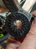
Eventually tracked down an adapter and the hub is now sitting in the dropouts with the torque arms. It took a fair bit of adjustment to make it fit. The 180mm rotor is very slightly rubbing the calipers. I think I need another washer but I don't have a spare washer wide enough to fit the axle nor a steel drill bit wide enough to make my own. I'll sort that tomorrow.

I've started to look at the wiring and I think I've sorted it out. But to be sure...

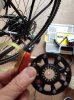
This is the wire connecting the motor to the controller. I guess matching the arrows in each part should do the trick. (very basic I know but I don't want to mess it up). It seems an unnecessarily long wire! I'll have to find somewhere to tuck it away.

20170819_170509 (2).jpg

The LCD connection (poor image)

LCD connector.jpg

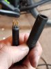
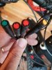
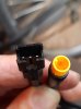
At the other end I assume the green connector is for the lcd, the reds for the brake levers (which I won't be using yet). Not sure what the orange connector is for.

20170819_170350 (2).jpg

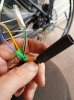
That just leaves the yellow PAS connection. I have a left sided PAS which has a different connection. I presume they'll have the same colour wires inside the sleeve and I can just cut and solder them?

20170819_170422 (2).jpg

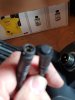
Finally this wire seems to be surplus??

20170819_170609 (2).jpg

I'd be grateful for confirmation that I'm on the right road:) I'd forgotten how fiddly all this is!

Thanks

John
 
D

Deleted member 4366

Guest
Yup. Everything is correct. The yellow connector with the two red and one green is for the throttle.

They always make the cables much too long, so you need a find a way to deal with that, like a tool-bag.

When you cut the connectors off the PAS tell us what colours you have if you're unsure which is which. Don't guess. Also, you should test the PAS before you put the crank back on so that you know you have it the right way round. You can't go by the arrows or use any other logic.
 

John L

Esteemed Pedelecer
Nov 23, 2007
287
6
Ah I forgot about the throttle:)

Yep I'll cut the wires and let you know. The PAS has a castellated edge that should fit into the crank case. But as you say I can't rely on logic:)

Sent from my SM-G950F using Tapatalk
 

John L

Esteemed Pedelecer
Nov 23, 2007
287
6
Ok the original PAS has red, black and white wires. The left sided PAS has brown, black and yellow! What do you think?

Sent from my SM-G950F using Tapatalk
 

John L

Esteemed Pedelecer
Nov 23, 2007
287
6
Red to brown. Black to black. White to yellow.
Excellent thanks:) The lcd is lighting up and the throttle works fine. I'll sort out the PAS in the morning. I'm happy with todays progress. Thanks. J

Sent from my SM-G950F using Tapatalk
 

John L

Esteemed Pedelecer
Nov 23, 2007
287
6
Unfortunately not a stir from the PAS. Soldering looks fine. I wonder is it anything to do with the lcd settings?

Sent from my SM-G950F using Tapatalk
 
D

Deleted member 4366

Guest
You've tried all four combinations of magnet disc orientation and rotation direction?

If that doesn't do it, try C1 =3 in the settings.
 
Last edited by a moderator:

John L

Esteemed Pedelecer
Nov 23, 2007
287
6
You've tried all four combinations of magnet disc orientation and rotation direction?

If that doesn't do it, try C1 =3 in the settings.
I'm using a dual hall sensor for left side crank, like this, which I ordered separately from BMSB. Everything is fixed. Its either facing in or out.

dual sensor.jpg

This is the PAS that came as part of the controller kit

original PAS.jpg

I can see that this one can have 4 combinations. I assumed that this was for the right crank only but I guess they can be turned around?

I have a feeling I've complicated this more than needs be!
 

John L

Esteemed Pedelecer
Nov 23, 2007
287
6
The original PAS worked fine when i reversed the sensor. Only problem is I can't remove the left crank nut to fit it:) Not a budge. Hmmm some sugru might be called for.

Sent from my SM-G950F using Tapatalk
 

John L

Esteemed Pedelecer
Nov 23, 2007
287
6
Well I went back to the dual sensor and changed the settings to C1=3 and hey presto:). It sorts out the headache of fitting the other sensor. Now to tidy up everything!

Sent from my SM-G950F using Tapatalk
 
  • Like
Reactions: Forge Custom

Forge Custom

Pedelecer
May 14, 2016
88
3
57
Dorset
Well done John! So just to be clear, you ended up using the original sensor that came with the controller and installed it on the right or left? Be good to see a picture of the final set up as I'm guessing I'll have the same issues as I'm getting the same kit!

Cheers

Matt
 

John L

Esteemed Pedelecer
Nov 23, 2007
287
6
Hi Matt.

I actually ended up using the second sensor (the 1 piece unit) and wired it as d8veh suggested. The original PAS had 8 magnets while the second had 12. So changing the C1 value to 3 tells the controller there is 12 magnets on the sensor. Its raining here so I haven't been able to road test it yet. But it works on the stand. J

Sent from my SM-G950F using Tapatalk
 

anotherkiwi

Esteemed Pedelecer
Jan 26, 2015
7,845
5,785
The European Union
Hi Matt.

I actually ended up using the second sensor (the 1 piece unit) and wired it as d8veh suggested. The original PAS had 8 magnets while the second had 12. So changing the C1 value to 3 tells the controller there is 12 magnets on the sensor. Its raining here so I haven't been able to road test it yet. But it works on the stand. J

Sent from my SM-G950F using Tapatalk
Depends on your version of the software and the sensor, in my first kit 03 wasn't even an active parameter and I used a 12 magnet disk that came with another controller on 8 magnet setting with no difference. Then I bought a K V12 sensor and that only works with 05, 06 and 07 setting.
 

John L

Esteemed Pedelecer
Nov 23, 2007
287
6
Depends on your version of the software and the sensor, in my first kit 03 wasn't even an active parameter and I used a 12 magnet disk that came with another controller on 8 magnet setting with no difference. Then I bought a K V12 sensor and that only works with 05, 06 and 07 setting.
I downloaded the lcd3 manual and it confirmed the setting. I took the long road but I learned a few things on the way:)

Sent from my SM-G950F using Tapatalk
 

rich_r

Pedelecer
Jun 23, 2017
89
32
50
North Yorkshire
My 12 magnet PAS only works on setting 08, which isn't a valid setting according to the LCD3 manuals I can find. I don't really care though as it works :)