
I thought Moigne Combe sounded familiar, just up the road from Ower Moigne. Some great named places around here... If you haven't been, the Scott Arms in Kingston is a lovely pub with views over Corfe Castle, and last time I went, some nice local ales.Yes, lovely spot, I enjoyed a long walk along a riverbank bridle path early morning yesterday to build an appetite for breakfast. I normally stay with my brother at Skippet Cottages, Moigne Combe but age means he's preparing to move into sheltered accommodation at Corfe Castle close to his daughter. I used the hotel and we ate out to avoid giving him extra work since he is getting a bit frail now.
EDIT: I forgot the mention the very old graves in the beer garden. Very odd thing to see...
Last edited:
C
Cyclezee
Guest
I can paint it any colour you like FunkyIt doesnt look very RED to me..........
Funky
")
Please be careful what you say, I have a strange feeling that other people can see what we write about on here
Of course that strange feeling is not the same as the other strange feelings I have for you
Last edited by a moderator:
C
Cyclezee
Guest
De Do Do Do, De Da Da Da is all I've got to say to youHa ha...Ha ha ha......
My brother will know that, he's never been one to miss fine ales in that area. He's always been in farming and first started work as a 15 year old with a Guernsey herd at Corfe Mullen. He's spent much of his life in Dorset for the 63 years since then.I thought Moigne Combe sounded familiar, just up the road from Ower Moigne. Some great named places around here... If you haven't been, the Scott Arms in Kingston is a lovely pub with views over Corfe Castle, and last time I went, some nice local ales.
EDIT: I forgot the mention the very old graves in the beer garden. Very odd thing to see...
I visit Moigne Combe and Corfe Castle regularly, did my early motorcycling in Dorset, years of boating on the Dorset coast and was stationed there in the Army decades ago in both Blandford Forum and Bovington, so it always feels like another home for me.
[QUOTE
Please be careful what you say, I have a strange feeling that other people can see what we write about on here
Of course that strange feeling is not the same as the other strange feelings I have for you[/QUOTE]
OMG.......surely not ???????
Never mind........as long as WE are enjoying the banter.......gives me a welcome break from painting furniture and spinning yarn.......and you DO make me laugh
So......this motor thingy.....who is getting it then ??
Eddieo will just abuse it now he has his fancy da doo run run rude thing.....
looks like its just 10mph in the running......I think he deserves it after having to wade through all our, er, 'chatting'
Funky
PS its NEXT weekend I'm over your way (evil laugh)
Please be careful what you say, I have a strange feeling that other people can see what we write about on here
Of course that strange feeling is not the same as the other strange feelings I have for you
[/QUOTE]OMG.......surely not ???????
Never mind........as long as WE are enjoying the banter.......gives me a welcome break from painting furniture and spinning yarn.......and you DO make me laugh
So......this motor thingy.....who is getting it then ??
Eddieo will just abuse it now he has his fancy da doo run run rude thing.....
looks like its just 10mph in the running......I think he deserves it after having to wade through all our, er, 'chatting'
Funky
PS its NEXT weekend I'm over your way (evil laugh)
Addendum to my bid in post2 of this thread.
I am making this addendum as late as I dare before the bidding closes at midnight. It is a bit like ebay where I try and bid in the last 5 or 10 seconds to reduce the possibility showing my hand and encouraging a competitor to out bid me. Looking through the thread so far it is hard to see that I have any serious competition, unless of course Cycleezee decides the best post prize goes to the most humorous line of "banter"; I would say comedy, but I don't think any of would qualify as a good joke.
So here are my additions which are designed to out bid any serious engineer who might be try making a last minute overbid.
1. Kind as Flecc was to offer to pay for delivery to me, and Cyclezee's insistence that he would post it for free, I will offer to collect the dud motor in person from Milton Keynes, subject to the condition that I can bring my Agattu in my car and we can exchange experiences perhaps have a ride together. After I got Kitchenman to bicycle 40 miles each way to deliver to me a £10 book which I bought off him (see here), I have decided my reputation for meanness would become too well established if I did not at least pick up the dud motor. Perhaps I can arrange pickup when you, Cycleezee, have one of your Sunday rides in MK. Also based on my experience with Kitchenman I have decided that actually meeting forum members face to face is an interesting and valuable activity for someone like myself who is comparatively inexperienced with these machines.
2. This morning, in preparation for the virtual certain success of my bid, I went especially to an amateur radio equipment rally and purchased useful test equipment: A dual channel HP 1740A oscilloscope, and a 4 digit multimeter of a non-descript manufacturer. These should prove very useful if I can get any life at all out of the motor and/or its control board. So this demonstrates the seriousness of my commitment.
3. Finally, if there is some electronic engineer around who is thinking of outbidding me, why not join forces with me in this opportunity to analyse this dud Panasonic motor? Working in collaboration we may learn more than one person can by himself.
Last edited:
C
Cyclezee
Guest
Congratulations 10mph, you are the winner by a huge margin
You are welcome to collect your prize, so PM or email me to make arrangements.
A ride would be good, but the next organised one is not until 7th August, see here MK CTC shorter rides
Alternatively, if you come to MK, we could go for a ride together next Saturday, Sunday or Monday.
You are welcome to collect your prize, so PM or email me to make arrangements.
A ride would be good, but the next organised one is not until 7th August, see here MK CTC shorter rides
Alternatively, if you come to MK, we could go for a ride together next Saturday, Sunday or Monday.
Congratulations 10mph after all that writing you deserve it ...... I had forgotten it was you who bought 'that interesting book' haha.
You could, of course, just arrange to meet up with these guys for a ride without having to buy/collect these strange items.......
Or are we really going to hear all about the motor autopsy ?
Either way, have fun ( dont forget the photos of the official handover )
Lynda
You could, of course, just arrange to meet up with these guys for a ride without having to buy/collect these strange items.......
Or are we really going to hear all about the motor autopsy ?
Either way, have fun
( dont forget the photos of the official handover )Lynda
C
Cyclezee
Guest
De Do Do Do, De Da Da Da is all I've got to say to youWell.....I for one am devastated! sitting here on lake Bled in Slovenia (cycling around lake today) I was really looking forward to winning and sticking this thing on ebay!
Thanks Cyclezee. I look forward to meeting on Sunday evening.
Scott, Funkyln: Thanks for the comments. I hope in due course to be boring everyone with long posts about my investigations. I am not particularly expecting anything of general use to come out- I am mainly satisfying my own curiosity about these interesting machines.
Scott, Funkyln: Thanks for the comments. I hope in due course to be boring everyone with long posts about my investigations. I am not particularly expecting anything of general use to come out- I am mainly satisfying my own curiosity about these interesting machines.
C
Cyclezee
Guest
It was nice to meet you and your lady wife yesterday Mike at the prize giving ceremony.
The crowd control proved a bit unnecessary and I had expected more media interest at such an auspicious occasion.........The News of The World at least
It will be interesting to see what you can glean from your investigations.
The crowd control proved a bit unnecessary and I had expected more media interest at such an auspicious occasion.........The News of The World at least
It will be interesting to see what you can glean from your investigations.
John,
Thank you very much for the dud Pansaonic motor, and also for the quick try out on your short hill of the bike with your front hub motor kit. It certainly pulled very strongly when I gingerly twisted the throttle slightly. I was impressed by both your bike workshop and by your wide knowledge of these machines.
With the help of the instructions on Flecc's website I have opened up the motor case this morning and had a look inside. I first tested the pedelec torque sensor resistance as suggested by Flecc on the other thread about your motor. It came out to 77 ohms and 77 ohms as Flecc's website says it should.
I also checked the motor winding continuity and it seems OK.
I think the next thing is to put some power on and see what happens, but I will probably have to make something to function as the handle bar power/mode switch unit and display - unless some kind person has an old handlebar unit surplus to requirements.
C
Cyclezee
Guest
Hi Mike,
Perhaps in the interests of science and furtherance of knowledge, a Panasonic dealer might just donate a switch unit to you. If for no other reason than you might be able to establish what the error code means and what caused it. This information could no doubt be useful to the trade and customers alike.
I would suggest contacting 50cycles, Onbike or Raleigh as they are the main suppliers of Panasonic powered bikes.
Good luck.
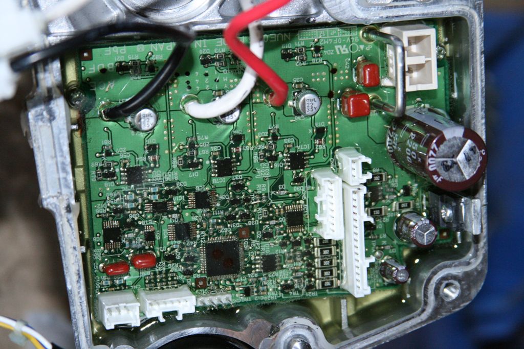
Main functional regions of circuit board
I have been able to identify the general function of some of the areas of the Panasonic controller board inside the dud motor.
First I note that the date is encoded as 28 May 2007. This seems to tie up with what Cyclezee said about the bike being purchased 3.5 years ago (ie about end of 2007). The date code is done with black dots painted by the board manufacturer before it is placed in the housing and encapsulated in potting.

Bottom centre and right are the 3 identical FET circuits which drive the three motor windings.
The area on the left processes the input current, and the heat sunk transistor may generate the switch mode waveform. The 2.2mF 50V capacitor may be used to provide a low impedance at the switching frequency and help reduce AC currents circulating in the battery leads.
Here is a picture of a later model which Flecc found on Emmanuel's blog on his page La qualité est dans les détails - Le blog d'Emmanuel
This picture is upside down compared with mine of the dud motor. The date code is either 10 or 26 Sept 2008, ie over a year later than the dud motor. Careful examination of this later model shows that the major changes is the provision of sockets on the board to take the battery connections and to the handlebar + unused connector loom. There are also 4 pins beside the hall sensor socket which are probably for a test connector. In the dud motor this test connection appears to have had the pins cropped off.
The rest of the circuit detail does not seemed to have changed a great deal between the 2007 version and the 2008 version.
One can go back further: Flecc has a photo of a 2006 or earlier model. This is considerably different. The processor/FPA is much larger - obviously an earlier version of the IC.

There is probably less to be learnt from this old version.
My main question now is:
Which 2 wires in the handlebar wiring loom do I have to short together to emulate the action of pressing the power on button? I think I need to do this to switch the battery power on to the controller board. I cant look at the colours of the wires in my 2011 handlebar unit, since the molding seems to be permanently sealed - no doubt to keep the rain out.
Does someone have an old handle bar unit -probably pre 2010 that they can look inside and tell me which colour wires go to the on/off button?
I have been able to identify the general function of some of the areas of the Panasonic controller board inside the dud motor.
First I note that the date is encoded as 28 May 2007. This seems to tie up with what Cyclezee said about the bike being purchased 3.5 years ago (ie about end of 2007). The date code is done with black dots painted by the board manufacturer before it is placed in the housing and encapsulated in potting.
Bottom centre and right are the 3 identical FET circuits which drive the three motor windings.
The area on the left processes the input current, and the heat sunk transistor may generate the switch mode waveform. The 2.2mF 50V capacitor may be used to provide a low impedance at the switching frequency and help reduce AC currents circulating in the battery leads.
Here is a picture of a later model which Flecc found on Emmanuel's blog on his page La qualité est dans les détails - Le blog d'Emmanuel
This picture is upside down compared with mine of the dud motor. The date code is either 10 or 26 Sept 2008, ie over a year later than the dud motor. Careful examination of this later model shows that the major changes is the provision of sockets on the board to take the battery connections and to the handlebar + unused connector loom. There are also 4 pins beside the hall sensor socket which are probably for a test connector. In the dud motor this test connection appears to have had the pins cropped off.
The rest of the circuit detail does not seemed to have changed a great deal between the 2007 version and the 2008 version.
One can go back further: Flecc has a photo of a 2006 or earlier model. This is considerably different. The processor/FPA is much larger - obviously an earlier version of the IC.
There is probably less to be learnt from this old version.
My main question now is:
Which 2 wires in the handlebar wiring loom do I have to short together to emulate the action of pressing the power on button? I think I need to do this to switch the battery power on to the controller board. I cant look at the colours of the wires in my 2011 handlebar unit, since the molding seems to be permanently sealed - no doubt to keep the rain out.
Does someone have an old handle bar unit -probably pre 2010 that they can look inside and tell me which colour wires go to the on/off button?
Attachments
-
 83 KB Views: 53
Last edited:
Mike, the 'transistor' with a heat sink is more likely to be a 5v regulator! What numbers / code are stamped on it?
Also could you check the continuity of each motor phase wire to earth? Continuity here would indicate one of the FETs has shorted.....
EDIT: I presume the FETs are mounted under the board?
Also could you check the continuity of each motor phase wire to earth? Continuity here would indicate one of the FETs has shorted.....
EDIT: I presume the FETs are mounted under the board?
Last edited:
Related Articles
-
 MTF Enterprises announces acquisition of EMU Electric Bikes
- Started by: Pedelecs
-
 Wisper 806T folding bike wins Which? ‘Best Buy’
- Started by: Pedelecs
-
 Sustrans calls for protected cycle lanes
- Started by: Pedelecs
-
 Amazon launch their first UK e-cargo micromobility hub
- Started by: Pedelecs
